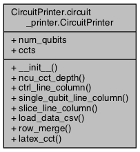
Public Member Functions | |
| def | __init__ (self, num_qubits) |
| def | ncu_cct_depth (self, num_ctrl) |
| def | ctrl_line_column (self, gate_name, ctrl, tgt, column_length) |
| def | single_qubit_line_column (self, gate_name, index, column_length) |
| def | slice_line_column (self, slice_name, column_length) |
| def | load_data_csv (self, csv_file) |
| def | row_merge () |
| def | latex_cct (self, data_file, file_name="cct", max_depth=16) |
Data Fields | |
| num_qubits | |
| ccts | |
Detailed Description
The CircuitPrinter class creates a quantum circuit .tex file for viewing the circuit output.
Assumes the availability of the quantikz LaTeX package when compiling. Preferably use lualatex
to ensure sufficient memory access.
Definition at line 1 of file circuit_printer.py.
Constructor & Destructor Documentation
◆ __init__()
| def CircuitPrinter.circuit_printer.CircuitPrinter.__init__ | ( | self, | |
| num_qubits | |||
| ) |
Definition at line 7 of file circuit_printer.py.
Member Function Documentation
◆ ctrl_line_column()
| def CircuitPrinter.circuit_printer.CircuitPrinter.ctrl_line_column | ( | self, | |
| gate_name, | |||
| ctrl, | |||
| tgt, | |||
| column_length | |||
| ) |
Creates a columnar slice of the circuit with the given gate name, control and target lines.
The number of qubits specifies the length of the column.
Definition at line 20 of file circuit_printer.py.
Referenced by CircuitPrinter.circuit_printer.CircuitPrinter.load_data_csv().
◆ latex_cct()
| def CircuitPrinter.circuit_printer.CircuitPrinter.latex_cct | ( | self, | |
| data_file, | |||
file_name = "cct", |
|||
max_depth = 16 |
|||
| ) |
LaTeX file outputter for quantum circuit generation.
Definition at line 124 of file circuit_printer.py.
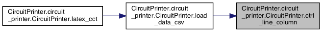
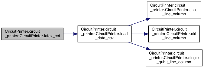
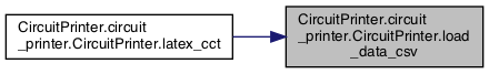
References CircuitPrinter.circuit_printer.CircuitPrinter.load_data_csv().
◆ load_data_csv()
| def CircuitPrinter.circuit_printer.CircuitPrinter.load_data_csv | ( | self, | |
| csv_file | |||
| ) |
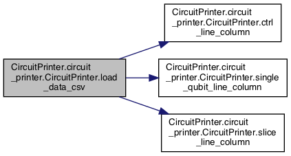
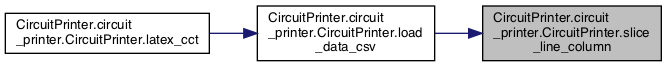
Loads the data from a CSV file. Assumes the following layout:
gate_name, control_qubit_number, target_qubit_number, gate_matrix_values
Definition at line 52 of file circuit_printer.py.
References CircuitPrinter.circuit_printer.CircuitPrinter.ccts, CircuitPrinter.circuit_printer.CircuitPrinter.ctrl_line_column(), CircuitPrinter.circuit_printer.CircuitPrinter.num_qubits, CircuitPrinter.circuit_printer.CircuitPrinter.single_qubit_line_column(), and CircuitPrinter.circuit_printer.CircuitPrinter.slice_line_column().
Referenced by CircuitPrinter.circuit_printer.CircuitPrinter.latex_cct().
◆ ncu_cct_depth()
| def CircuitPrinter.circuit_printer.CircuitPrinter.ncu_cct_depth | ( | self, | |
| num_ctrl | |||
| ) |
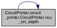
Calculate the required depth for the circuit using the implemented nCU decomposition
Definition at line 11 of file circuit_printer.py.
References CircuitPrinter.circuit_printer.CircuitPrinter.ncu_cct_depth().
Referenced by CircuitPrinter.circuit_printer.CircuitPrinter.ncu_cct_depth().

◆ row_merge()
| def CircuitPrinter.circuit_printer.CircuitPrinter.row_merge | ( | ) |
WIP: Merges rows between independent qubit operations to reduce printed circuit size
e.g. [I, I, I, X], [I, Z, I, I] -> [I, Z, X, I]
Definition at line 100 of file circuit_printer.py.
References CircuitPrinter.circuit_printer.CircuitPrinter.ccts.
◆ single_qubit_line_column()
| def CircuitPrinter.circuit_printer.CircuitPrinter.single_qubit_line_column | ( | self, | |
| gate_name, | |||
| index, | |||
| column_length | |||
| ) |
Creates a columnar slice of the circuit with the given gate name, on index
The number of qubits specifies the length of the column.
Definition at line 31 of file circuit_printer.py.
Referenced by CircuitPrinter.circuit_printer.CircuitPrinter.load_data_csv().

◆ slice_line_column()
| def CircuitPrinter.circuit_printer.CircuitPrinter.slice_line_column | ( | self, | |
| slice_name, | |||
| column_length | |||
| ) |
Creates a columnar slice of the circuit with a dashed line denoting the marked section
Definition at line 41 of file circuit_printer.py.
Referenced by CircuitPrinter.circuit_printer.CircuitPrinter.load_data_csv().
Field Documentation
◆ ccts
| CircuitPrinter.circuit_printer.CircuitPrinter.ccts |
Definition at line 9 of file circuit_printer.py.
Referenced by CircuitPrinter.circuit_printer.CircuitPrinter.load_data_csv(), and CircuitPrinter.circuit_printer.CircuitPrinter.row_merge().
◆ num_qubits
| CircuitPrinter.circuit_printer.CircuitPrinter.num_qubits |
Definition at line 8 of file circuit_printer.py.
Referenced by CircuitPrinter.circuit_printer.CircuitPrinter.load_data_csv().
The documentation for this class was generated from the following file:
- /Users/mlxd/Desktop/intel-qnlp-rc2/modules/py/pkgs/CircuitPrinter/circuit_printer.py